Where is the steel?
Where is the steel?
Since the trusses are incapable of resisting the wind loading, we know that the «official» explanation of the WTC collapse is false. If the floor joists (supports) were not the claimed trusses, then what were they? They had to be strong enough to support the floor slab and stiff enough to resist the wind loading. In fact, they had to be large steel beams. This is not to say that trusses were not used at all in the construction, but just that (contrary to the «official» line) the main floor joists were steel beams and not trusses.
The above argument using wind loading is certainly enough to tell one that trusses were not really used as the floor joists, but there are also other ways to determine this. Another approach is adopted in this section. We will:
• Calculate the weight of steel theoretically used in the construction of one of the towers assuming that the floor joists were trusses.
• Compare the result of this calculation to the 96,000 tons of steel known to have been used in the construction of each of the towers.
• Note that the calculated weight of steel is only 67 percent of the required 96,000 tons.
• Conclude that the 32,000 tons of steel unaccounted for, is due to the fact the the floor joists were actually weighty steel beams and not flimsy trusses (and thus that the official story is a lie spun to explain away what were obviously demolitions).
• Calculate a rough cross-sectional area for the steel beams that did serve as floor joists.
Since a cubic foot of steel weights 490 pounds, it is enough to deal with volumes rather than weights. We will calculate the volume of steel on a per floor basis.
To calculate the per floor volume of steel used in the construction of the twin towers, we will divide the calculation into three parts, namely, the volume of steel in the perimeter wall, the volume in the central core and the volume used in the floor support system.
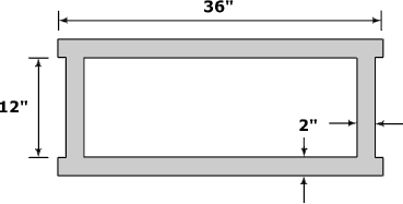
The perimeter wall was comprised of box columns welded to large spandrel plates. Two typical prefabricated sections are illustrated below. Each consists of three spandrel plates welded to three box columns and each is three floors high.
The first figure below shows the cross section of one of the perimeter box columns and its surrounds. The second and third figures detail the dimensions of two actual perimeter columns that were salvaged from the rubble.
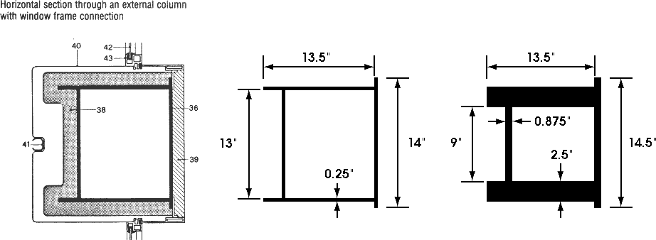
The numbers in the figure denote:
• 36 — the steel column
• 38 and 39 — fire resistant plaster
• 40 — aluminum facade
• 42 — window glass
• 43 — the window frame.
To obtain an estimate of the «typical» perimeter column, the dimensions of the perimeter columns listed in the WTC Steel Data Collection documentation were averaged. Whether this accurately reflects the true distribution of perimeter column thickness, is unclear, but it is all one has to go on (till those who hold the architectural details release them).
So, our «average» perimeter column has dimensions:
d = 13.4, t_w = 0.48, b_f = 12.9, t_(tf) = 0.32 and t_(bf) = 0.32.
and cross-sectional area:
2 x (13.4 x 0.48) + (12.9 x 0.32) + (14 x 0.32) = 21.5 square inches,
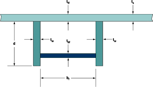
The parameters d, t_w, b_f, t_(tf) and t_(bf) are as in the following diagram from Appendix D which is part of the report found at http://www.house.gov/science/hot/wtc/wtcreport.htm.
For the time being we will ignore the column end plates and the spandrel beams. Since each floor is 12 feet high, the per floor volume of steel in an average perimeter box column is:
12 x 21.5/144 = 1.792 cubic feet.
In total there are 240 such columns, so the volume of steel so far is
240 x 1.792 = 430 cubic feet.
Now lets deal with the volume of steel in the column end plates. Each end plate is 14 inches wide by 11.75 inches deep and 1.375 inches thick, giving a volume of
14 x 11.75 x 1.375 = 226.2 cubic inches = 226.2/1728 = 0.130896 cubic feet.
Since, on each floor, one third of the columns are joined, and each join involves two end plates, the per floor volume of steel in the end plates is
2 x 0.130896 x 240/3 = 20.9433 cubic feet.
The spandrel plates are large, being 52 inches high and 3/8 inches thick. Each floor has the equivalent of one spandrel beam that stretches 4 x 207 = 828 feet right around the building. The volume is easily calculated to be
828 x 12 x 52 x 3/8 = 193752 cubic inches = 193752/1728 = 112.125 cubic feet.
So the overall per floor volume of steel in the perimeter wall is
430 + 21 + 112 = 563 cubic feet.
Now, we wish to calculate the per floor volume of steel in the core section of the building. To do this, we first need to calculate the volume of steel in each of the core columns. This is complicated by the fact that the dimensions of the columns reduced in size with increasing height. For example, at the base of the WTC some of these columns were 36 inches wide by 16 inches deep and 4 inches thick, whereas at the top, these box columns had transitioned to H-sections (I-sections) fabricated from 3/4 inch steel (the transition to H-sections occurred at floor 85). We will ignore the reduction in width and breadth of the columns, and only take into account the reduction in column thickness by assuming an average thickness of 2 inches (this roughly corresponds to a reduction in thickness of one quarter of an inch, every seven floors, up to floor 85). In reality, the column width and breadth decreased quite considerably and we only make this very generous assumption as the actual reductions in the width and breadth are unknown. So, we assume each core column has the following cross-section:
The cross-sectional area is (36 + 12 + 36 + 12) x 2 = 192 square inches = 192/144 = 1.333 square feet. Since each floor is 12 foot high, the per floor volume of steel in one such column is 12 x 1.333 = 16 cubic feet. Reports as to the number of core columns vary from 44 to 47. Once again, we will be generous in our assumptions and choose the higher figure of 47. Thus, the total volume of steel (per floor) in the core columns is
47 x 16 = 752 cubic feet.
On each floor, the core columns were bound together by a rectangular grid of beams. As the dimensions of these beams are not known we will assume they were, 14 inch by 14 inch box sections fabricated from 3/4 inch steel. Again, this is a very generous assumption. The cross-sectional area of such a box section is:
( 2 x 14 x 0.75 ) + ( 2 x 12.5 x 0.75 ) = 39.75 square inches = 39.75/144 = 0.276 square feet.
The core section is 137 feet wide x 87 feet deep. Hence, our rectangular grid comprises six 137 foot sections and eight 87 foot sections, for a total length of 822 + 696 = 1518 feet. Additionally, the outer two 137 foot sections have to extend to the perimeter wall (to give support for the trusses). Actually, the «official» version has a much smaller U shaped beam, but as I have mentioned above, we are being very generous. This adds another 140 feet to the length. The volume of the 1518 + 140 = 1658 feet of box section is:
1658 x 0.276 = 458 cubic feet.
Thus the overall volume of steel in the core section is:
752 + 458 = 1210 cubic feet.
We now turn our attention to the floor support system.
The floor slab was poured on 1.5 inch corrugated 22-gauge steel decking. Now, 22-gauge steel is 0.0336 of an inch thick. The corrugations lead to 1.25 square feet of steel decking for every square feet of floor slab. Hence, the volume of steel involved is:
207 x 207 x 1.25 x 0.0336/12 = 150 cubic feet.
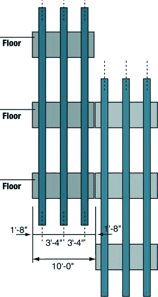
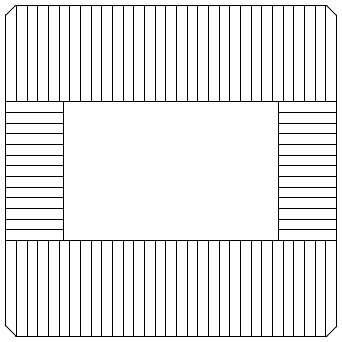
To complete our calculations, we need to calculate the volume of steel used in the system of trusses which supposedly supported the concrete floor slabs. The following graphic illustrates the truss system. The double trusses (of which, in this graphic, we only have an end view) ran perpendicular to the transverse trusses, and were essentially two transverse trusses bound together.
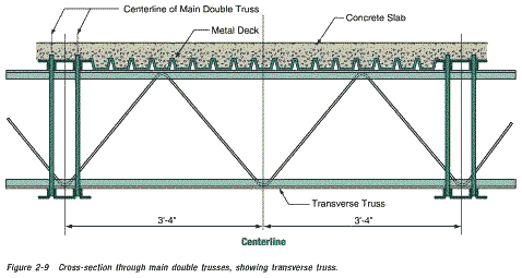
Consider one of the 3 foot four inch (40 inch) sections illustrated in the above graphic. The diagonal rod has a diameter of 1.09 inches (radius 0.545 inches) and a length of twice the square root of 20 squared plus 30 squared, that is, a length of
2 x srt( 20^2 + 30^2 ) = 2 x srt( 1300 ) = 72 inches.
Here, srt stands for the square root.
The cross-sectional area of the rod is 3.14 x 0.545 x 0.545 = 0.933 square inches. Hence the volume of rod in this segment is 72 x 0.933 = 67.2 cubic inches.
This gives a volume of 67.2 x 12/40 = 20.16 cubic inches per foot of truss.
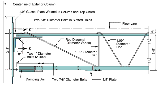
Pictured above, is the connection of one of the double trusses to the perimeter wall. The cross section marked X—X in this graphic, is pictured below. Note that the original graphic from the WTC-report was so out of scale, that it was necessary to stretch it somewhat.
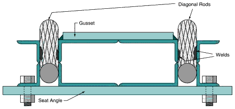
The first image below is apparently the real life version of the above graphic (supposedly obtained from the WTC wreckage). The second image shows the gusset plate and seat connection.
The dimensions quoted in the following section were made by taking measurements from these two photos. Standard adjustments for perspective had to be made for measurements from the second photo.
The gusset plate is 4 x 2 x 3/8 and has a volume of 3 cubic inches. The seat angle has a volume of roughly 2 x ((9 + 4) x 14.5 x 3/8) = 141 cubic inches and the «stiffeners» add another 9 x 1.5 x 3/8 = 5 cubic inches. Since there were (at most) 120 gusset plates and seat angles, these add in 120 x 149 = 17880 cubic inches. The 76 horizontal diagonal brace plates add in another 76 x 90 x 3/2 x 1/2 = 5130 cubic inches for an addition of (17880 + 5130)/1728 = 13.3 cubic feet of steel to our total.
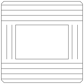
The upper chord (top section) of one of the double trusses consisted of four pieces of 1/8 inch thick angle iron, as illustrated below (it is circled in red).
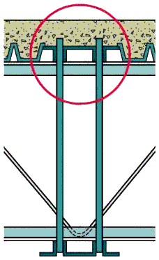
Below, is a more detailed view of the cross section of the top chord of a transverse truss (left) and double truss (right).
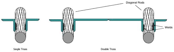
So, the upper chord has a cross sectional area of
((2 + 1.25) + (1.25 + 2))/8 = 0.8125 square inches for a transverse truss and,
((2 + 1.25) + (1.25 + 7 + 1.25) + (1.25 + 2))/8 = 2 square inches for a double truss.
Since we have no information concerning the lower chord (and the «official» pictures are inconsistent and nowhere near to scale) we will assume it has the same dimensions as the upper chord.
Now summing the volume of steel in the top and bottom chords and diagonal rods, we have the following per foot volumes:
2 x 0.8125 x 12 + 20.16 = 39.7 cubic inches per foot for the transverse trusses, and
2 x 2 x 12 + 2 x 20.16 = 88.3 cubic inches per foot for the double trusses.
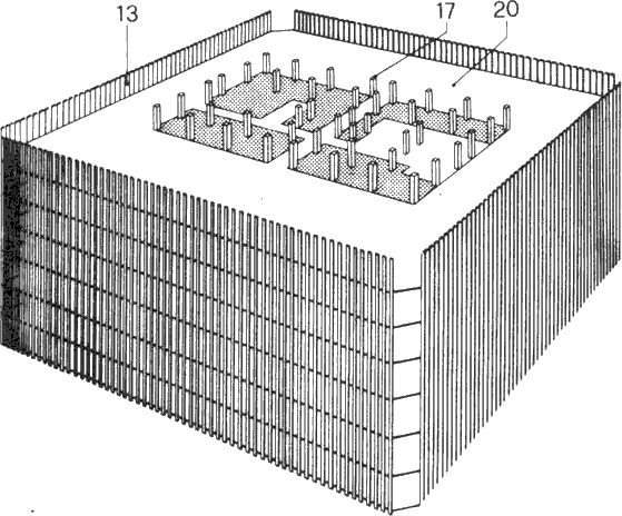
Now we need to calculate the total length of double and transverse trussing. There were apparently, 60 double trusses spanning the 60 feet from the perimeter wall to (a beam attached to) the core and 24 double trusses spanning the 35 feet from the perimeter wall to the core. They are pictured in the following graphic:
The overall length of double trussing was thus 60 x 60 + 24 x 35 = 4440 feet. Transverse trusses ran perpendicular to the double trusses as illustrated:
The overall length of transverse trussing was thus 8 x 207 + 4 x 87 = 2004 feet.
There was also a lesser supporting feature called «intermediate support angle». Since all we know about the intermediate support angle, is that its support capabilities were inferior to the double and transverse trusses, we shall be generous and assume that it was similar in nature to the transverse trusses. This adds another 1764 feet, to give a total of 2004 + 1764 = 3768 feet of transverse trussing.
Hence, the volume of steel in the double trusses was 4440 x 88.3/1728 = 227 cubic feet.
And the volume of steel in the transverse trusses was 3768 x 39.7/1728 = 86.6 cubic feet.
So the overall per floor volume of steel in the floor support system was
150 + 13.3 + 227 + 86.6 = 477 cubic feet.
The total per floor volume of steel, is now the sum of that in the perimeter wall, the central core section and the floor system. This is 563 + 1210 + 477 = 2250 cubic feet.
So why have we gone to all this trouble to calculate the per floor volume of steel? Well, we know that 96,000 tons of steel was used in the construction of each of the WTC towers. The WTC towers had 117 floors (110 above and 7 below the Plaza level) so an average floor contained 96,000/117 = 820 tons of steel. Since the density of steel is 490 pounds per cubic foot, we see that each floor contained about 820 x 2000/490 = 3347 cubic feet of steel.
Now, according to the above calculations, the per floor volume of steel in each of the towers, is (a very generous) 2250 cubic feet. But this is only 67 percent of the volume of steel that we know was used in the construction of the tower. So, the big question is: Where is the other 33 percent? Where are the missing 32,000 tons of steel? What features of the building are being left out of the «official» explanations?
Could it be that each concrete floor was actually supported by weighty steel beams and not by the very flimsy trusses of the «official» story?
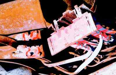
Well, the following picture, taken during the construction of the WTC, may hold the answer.
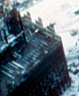
Here, one can see what appear to be large steel girders laid out according to the plan for the positioning of the supposed double trusses (this plan is pictured here). To make things clearer, the position of the girders have been marked in white in the photo below. Remember, that the perimeter columns which appear like a row of toothpicks in the visible sections of the wall, are actually 14 inches wide. Thus the floor joists do indeed appear to be quite large steel girders. One thing is certain though, they are not the claimed double trusses.
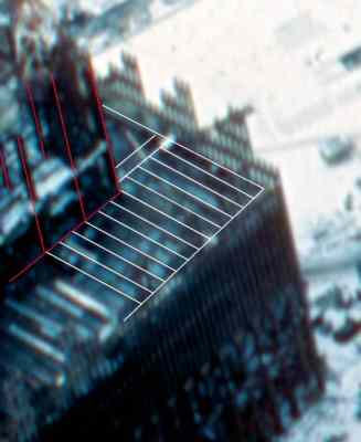
In this photo the vertical red lines correspond to visible core columns. The white lines (apart from the outer perimeter lines) correspond to visible floor joists.
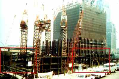
Above, is a photo of early construction work on the South Tower. Behind, is the North Tower and further back, the Verizon building. The photo was taken from the old extention of Greenwich Street (which was ripped up to make way for WTCs 4 and 5) looking north west. Some interesting aspects of the construction are presented in the following enlargements of the red-boxed regions.
In this enlargement one can see eight perimeter box columns at ten foot intervals (further up the structure these columns split into three smaller box columns at 40 inch intervals). Of course, what is of interest here are the eight (seven on the lower level and one on the upper) quite solid looking beams spanning the 35 foot gap between the perimeter wall and the central core, where the «official line» promised us there were only flimsy trusses.
In the foreground of this enlargement one can see eighteen perimeter box columns of the South Tower (those in the background are of the North Tower). If you look closely, you can just make out a single quite large beam spanning the 60 foot gap between the central core and the perimeter wall. Remember, that the corner core column to which this beam is attached is some 3 foot wide (and 16 inches deep). However, one floor below this, workers are working on a section of flooring held up by what appears to be trussing. One supposes that this is temporary flooring. If one looks carefully one can see a barrier rail to prevent workers from falling off the area supported by the trusses. This tends to support the case that this is temporary flooring.
Assuming that all the missing steel is contained in these beams we can estimate their cross-sectional area (the assumption that all the missing steel is contained in these beams is somewhat dubious, as I suspect that the sample of perimeter columns has been deliberately biased toward columns with thin cross-sections, and hence, that a significant percentage of the missing steel, is missing from the perimeter columns). Still, using this assumption, we have 1100 + 227 = 1327 cubic feet of steel to play with (the 227 comes from the no longer necessary double trussing). The total length of double trussing to be replaced is 4440 feet. Hence, the desired estimate of the cross-sectional area is:
1327/4440 x 144 = 43 square inches.
So, we have enough steel to replace the double trusses by H-beams (or I-beams, depending on how you view them) that are 24 inches deep, 10 inches wide and fabricated from one inch thick steel. These would be very, very strong beams, and would be much, much stronger than necessary to span the 35 and 60 foot spans from the central core to the perimeter wall.
It is worth emphasizing that these beams, plus the thicker stronger perimeter columns, would mean that WTC One and Two were actually traditional steel-framed buildings, that also incorporated extra thinner perimeter columns, to attain the rigidity necessary to resist wind loading.
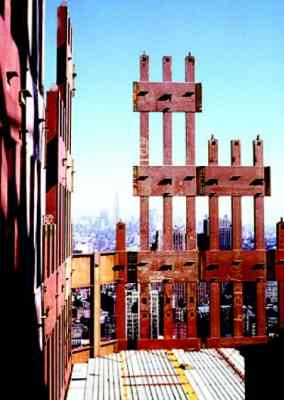
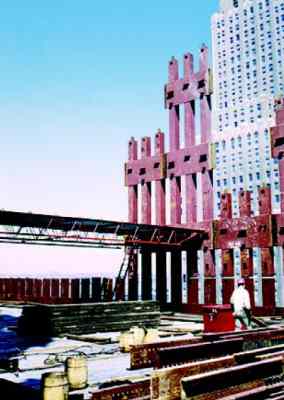
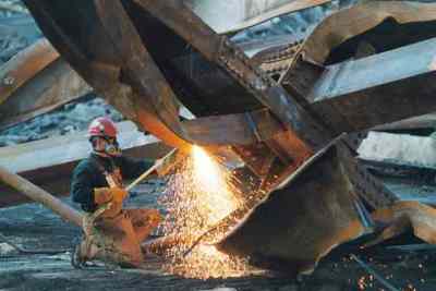
Above are pictures taken during the construction of the WTC. On the right is a picture of some 30 feet of trussing, which one supposes was temporary flooring. Note the vertical gaps in the box columns of the perimeter wall. Gaps in the box columns do not seem to be a sensible feature in a supposedly load bearing wall. Is this because the perimeter wall was not actually meant to be a load bearing wall as such, but a feature designed to give the WTC its required rigidity (against wind loading)? In the left photo note the yellow and red lines in the concrete. In the right photo note the three parallel light-colored lines (about 4 inches wide) in the concrete. One also wonders why the pile of steel in the foreground was hoisted up the building, unless it was to be incorporated in the structure. An answer to this question may be provided by the following photo.
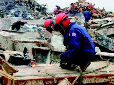
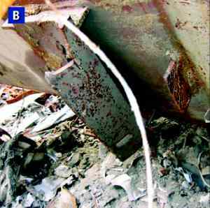
Between the workers cutting up a couple of WTC core columns, is a column with concrete still attached to the beams that are welded/bolted to it. These U-shaped beams look suspiciously like the lengths of steel in the foreground of the picture of the trussing. Is it possible that floor slab was some eight inches thick and laced with significant steel beams? Was the slab poured in situ and not prefabricated as some claim? Was the temporary flooring only necessary till the concrete in the floor slabs had set? And where does the following piece fit in the whole affair?
Более 800 000 книг и аудиокниг! 📚
Получи 2 месяца Литрес Подписки в подарок и наслаждайся неограниченным чтением
ПОЛУЧИТЬ ПОДАРОКЧитайте также
СТИЛЬ — СТАЛЬ STEEL — STYLE
СТИЛЬ — СТАЛЬ STEEL — STYLE Елена Маслова 22 апреля 2002 0 СТИЛЬ — СТАЛЬ STEEL — STYLE (От оружейников — к ювелирам...) Об украшениях, сделанных из нержавеющей стали и стремительно приобретающих популярность, рассказывает известный московский дизайнер-стилист. Хромоникелевая